
DC2200
The DC2200 LED Driver is designed to power many of Thorlabs' LEDs, including the Solis High-Power LEDs for Microscopy, Thorlabs' Mounted LEDs, and Thorlabs' Fiber Coupled LEDs. The driver can provide a maximum LED current of up to 10 A and maximum forward voltage of up to 50 V. A list of current / forward voltage combinations outlined in the table to the right.
The back panel includes two LED connection terminals for compatibility with all of Thorlabs' high-power and mounted LEDs. The LED1 terminal is a female 12-pin Neutrik MiniCON connector that accommodates high-power LEDs that require drive currents up to 10 A. The LED2 terminal has a female 4-pin M8x1 connector designed for lower-power LEDs that require drive currents of ≤2 A. The two inputs are visible in the back view of the driver housing shown above. LED compatibility information is provided in the LED Options table below. While two LEDs can be connected to the driver, only one LED can be driven at a time. For cases where two LEDs are connected simultaneously, the front panel of the driver can be used to select which LED recieves the drive current.
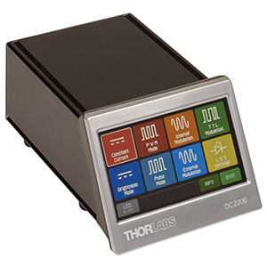
The driver can either be controlled locally via the device front panel, as shown in the screenshot above, or from a PC using the USB 2.0 port on the back of the device and the included software package (see the Software tab). The main menu of the front panel's touch screen display allows the user to select between operating the LED in constant current mode or brightness mode, internally or externally pulsed modes, and TTL modulation. In addition to reading data stored in the EEPROM memory of LEDs with this feature, the driver can also initiate a test procedure to measure the LED forward voltage, from which it can determine the maximum current limit. More information on the operating modes can be found on the Display tab. In addition to the USB 2.0 port and LED connection terminals, the back of the housing includes an SMA input for the external modulation signals, an interlock circuit that can be connected to a user-supplied emergency off switch, and grounded jack that can be used with ESD protection equipment. See the Front & Back Panel tab for a diagram of the back of the housing. Each DC2200 includes two auxiliary cables for connecting custom LEDs for the driver. One cable has a male 12-pin Neutrik MiniCON connector that is compatible with the LED1 terminal. The second cable (Item # CAB-LEDD1) has a male M8x1 connector compatible with the LED2 terminal. Additional CAB-LEDD1 cables are available for purchase separately below.
Specification
LED Current /Max LED Forward Voltagea : 1.5 A / 50.0 V
2.0 A / 35.0 V
LED Current Accuracy : ±(0.1% + 1 mA)
LED Current Resolution : 0.1 mA
Waveforms : Sine, Square, Triangle
Frequency Range : 20 Hz to 100 kHz
Small Signal Bandwidth DC: - 250 kHz